Maintaining your Anchor Tools
As with most mechanical devices, CHANCE® anchor-installing tools periodically require maintenance checks to ensure peak performance.
As with most mechanical devices, CHANCE® anchor-installing tools periodically require maintenance checks to ensure peak performance.
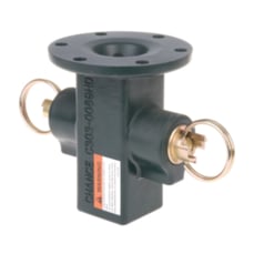
SHEAR PIN LIMITER
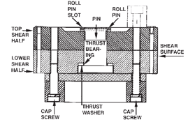
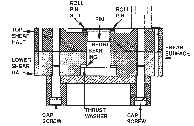
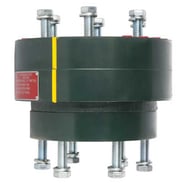 In the case of the shear-pin torque limiter, (see drawing and photo) you should be able to rotate the tool shear halves independently from one another using a smooth-turning action. If rotation cannot be done by hand or if movement is challenging, disassemble the torque indicator to check the thrust bearing, washers and/or pin for wear.
If the halves are dull, they need to be sharpened by surface grinding. A local machine shop can perform this service. When reassembling the indicator, coat thrust-bearing pin, washers and shear surface with grease.
Secure top shear half to the lower half by tightening the center bolt snugly. Back off one roll-pin slot and lock with roll pins. Check cap screws for wear and replace if necessary. Torque cap screws to minimum of 60 ft.-lbs. All output string bolts used in the drive-train system should be checked for tightness.
Loose or damaged bolts may fail at or below the anchor’s torque rating and contribute to damage elsewhere within the tool assembly. Replacement components are available.
Video: Shear Pin Torque Limiter Instruction Video
Video: Shear Pin Torque Limiter Repair Video
LOCKING-DOG ASSEMBLY
 The CHANCE® locking-dog assembly is another mechanical-anchor installing device that needs periodic inspection. When the locking-dog assembly is correctly positioned and in good working order, it performs smoothly and freely ensuring complete and positive capture of the anchor installing wrench drive tube and anchor rod.
If locking dogs do not rotate smoothly or engage easily into the “in” and “out” positions, wrench and rod capture may not be correct. Under such circumstances, if dogs are worn or damaged, order new ones. When inspecting the locking-dog assembly, ensure the set screws holding the two-dog assemblies are in position. There are two assemblies, one below each dog:
- The innermost set screw is 1⁄2” x 5⁄8”
- The outermost screw is 1⁄2” x 3⁄8”
The square socket with the wrench drive tube is another section of the locking-dog assembly that needs vigilant inspection. The socket can become worn from long-term use and/or poor wrench drive-tube alignment. Under such circumstances, the drive-tool end can become damaged. By monitoring the 1-1⁄8” holes located at the top of the wrench-drive tube for wear, you can detect square socket wear that is beginning to damage the wrench.
A drive tube wear at the 1-1⁄8” hole shows the locking-dog assembly is acquiring torsional load on the wrench-drive wall inside the holes. Such wear indicates you need a new locking-dog assembly. Locking Dog Repair Kits can be found online.
Watch these videos for more information:
Video: PISA Installation using Locking Dog
Video: Locking Dog Repair Video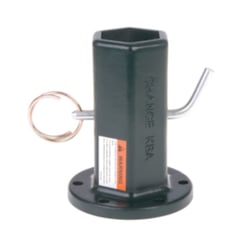 KELLY-BAR ADAPTER
When ordering tooling for a new truck, the Kelly bar should be measured across the flats to establish the proper size between the truck Kelly bar and Kelly-bar adapter.
CHANCE number 630012HD Kelly-bar adapter has a 2-5⁄8” hex inside diameter. This particular adapter is often confused with a 630011HD adapter with 2-1⁄2” hex. If a 630012HD is used on a 2-1⁄2” hex, the Kelly bar tends to round out the hex socket of the Kelly bar adapter. In this case, the pin holding the Kelly bar adapter to the Kelly bar will begin to take up load and elongate the hole. This will eventually split-out the top of the Kelly bar adapter.
RETAINING PIN
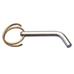 The retaining pin holds the Kelly bar adapter to the Kelly bar with a loose fit so the retaining pin will not take up load. The pin consists of a bent arm and klik pin. This gives a positive connection at both ends of the pin to protect operators from accidental pin ejection due to drive-train torsional forces.
Before any anchor installation, always check output bolts to ensure they are tight. Lost or damaged bolts can cause failure at or below the anchor torque rating or contribute to damage elsewhere on the output string. Check all tools and parts for wear or damage and replace as necessary.
SUMMARY
During anchor installations maintain adequate down pressure and keep the anchor-drive wrench in alignment with the anchor to prevent uneven wear or damage to the tool. Misalignment puts an extremely high stress on the end of the wrench where the wrench fits over the anchor. This can possibly cause the drive tube to split on the end.
Check all tools and parts for wear or damage and replace as necessary. If used properly, tools will provide extended service with minimal service requirements.

Recommended Posts

Get High Performance with New PCORE® High-Voltage PRC® Bushings
Enhance Safety During Live-Line Maintenance With Barry D.E.W. Line® Insulating Tag Lines